3D Designer
User Guide
How to design your own 3D-printable models, step by step.
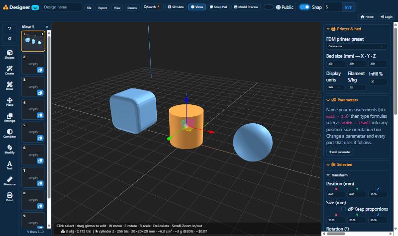
For the 3D Designer on the website and the 3D Designer app for Windows and Mac. October 2026.
Contents
- Getting started
- The screen
- Looking around your model
- Adding shapes
- Selecting and moving parts
- Size, position and colour
- The right-click menu
- Placing parts
- Joining parts, holes and cuts
- Changing a shape
- Drawing your own shapes
- Ready-made parts and makers
- Text, pictures and colour
- Measuring
- Copies, mirrors and groups
- Build views
- Getting ready to print
- Saving and opening designs
- Downloading for your printer
- Keyboard shortcuts
- Other useful things
- Problems and fixes
- Quick reference card
1Getting started
With the 3D Designer you can make things to 3D print, like a box with a lid, a name tag, a spare knob or a gift, in your web browser. You build with simple shapes. You put them together, cut holes, add text and then download a file for your printer.
What you need
- A computer with Chrome, Edge, Firefox or Safari, or the 3D Designer app for Windows or Mac.
- A mouse with a scroll wheel. A trackpad works, but a mouse is easier.
- A free account on 3d-lithophane.com if you want to save designs online and download them for printing. You can try everything without one.
Free and Supporter
Nearly everything in the Designer is free. A few extras, such as the AI that designs a model from a description and some of the download formats, need a Supporter membership. They have a small padlock next to them. Your plan is shown at the top right of the Designer.
Your first model
- Open the Designer, click Shapes on the left and pick Cube.
- On the right, under Size (mm), type 40, 40 and 10.
- Add a Cylinder, make it 10 × 10 × 20 and move it to the middle of the cube.
- Right-click the cylinder and choose Combine > Mark as hole. Then choose Combine > Apply holes. The cube now has a hole in it.
- Type a name at the top and choose Export > STL. Open the file in your printer's software and print it.
2The screen
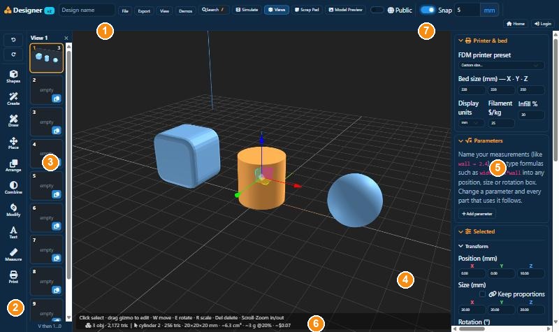
- 1Top bar. The name of your design and the menus: File (save, open, import), Export (download for printing), View, Demos, Search, Simulate, Views, Scrap Pad and Model Preview.
- 2Tool rail. All the tools, sorted into groups: Shapes, Create, Draw, Place, Arrange, Combine, Modify, Text, Measure and Print. Click a group to see what is in it. Undo and Redo are at the top.
- 3Build views. Small pictures of your ten build plates. See chapter 16.
- 43D view. Your printer bed with the model on it. Each grid square is 10 mm.
- 5Right panel. Your printer and bed size, and the position, size and colour of the part you have selected.
- 6Status line. The number of parts, the size of the selected part, and roughly how much filament it needs and what it costs.
- 7Snap. When it is on, parts move in fixed steps (5 mm here), which makes it easy to line them up.
3Looking around your model
You can look at your model from any side. This only changes your view. The parts stay where they are.
| To | Do this |
|---|---|
| Turn around | Hold the left mouse button on an empty spot and drag. |
| Slide sideways | Hold the right mouse button and drag. |
| Zoom in or out | Roll the scroll wheel. It zooms in towards the mouse pointer. |
| Jump to a view | Press 1 (at an angle), 2 (front), 3 (side) or 4 (top), or use the View menu. |
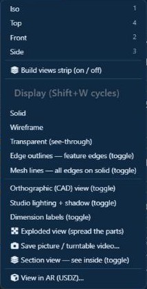
More in the View menu
- Wireframe and Transparent let you see through parts, for example to check that a hole goes all the way through. Shift + W switches between the display styles.
- Section view cuts the model open on screen so you can see inside.
- Dimension labels shows the sizes of the selected part in the 3D view.
- Save picture / turntable video saves an image or a short video of the model turning round, to share.
- View in AR lets you see the model in your room on a phone or tablet.
4Adding shapes
Click Shapes at the top of the tool rail, then click a shape. It is placed on the bed and selected, so you can change it straight away.
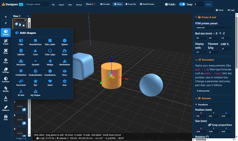
- Most models start with a Cube, Rounded box, Cylinder or Slab / plate.
- A Tube / pipe is a cylinder with a hole through the middle. A Dome is half a sphere.
- My Shapes holds the parts you saved yourself. To save one, right-click it and choose Object > Save as my shape. You can then use it in any design.
5Selecting and moving parts
Selecting
- Click a part to select it. It turns orange.
- Hold Shift or Ctrl while you click to select more than one part.
- Click an empty spot to select nothing. Ctrl + A selects everything, and Tab goes from one part to the next.
- The Objects list at the bottom of the right panel shows all your parts. Click a name to select that part. The small buttons next to it hide, lock or download the part.
The arrows on a selected part
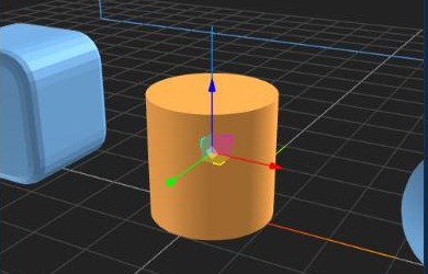
Drag an arrow to move the part in that direction only. Drag one of the small squares between the arrows to move it flat over the bed. There are three sets of arrows:
| W | Move arrows to move the part |
| E | Rotate rings to turn it |
| R | Scale handles to make it bigger or smaller |
Small and exact moves
- The arrow keys move the selected part one snap step at a time. Hold Shift for steps of 0.2 mm.
- Move with snapping (Shift + M): click a corner, edge or face of a part, then click where it must go. It snaps onto the corners and edges of other parts. You can also type a distance and press Enter. Hold Ctrl to move a copy and leave the original where it is.
6Size, position and colour
The right panel shows the numbers of the selected part. Click in a box, type a new number and press Enter. All sizes are in millimetres.
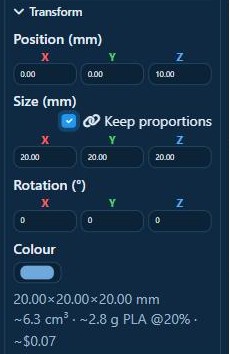
- Position is where the part sits on the bed. X is left and right, Y is front and back, Z is the height.
- Size is the width (X), depth (Y) and height (Z) of the part.
- Keep proportions: tick this and change one size, and the other two change with it, so the part doesn't get stretched. It works with the scale handles too, and the Designer remembers the tick for next time.
- Rotation turns the part by the number of degrees you type, for example 90.
- Colour is the colour of the part. Colours are kept when you download a 3MF file for a multi-colour printer.
Under the colour you can see the size of the part, its volume, and about how much filament it uses and costs. The Actions buttons do common jobs in one click: drop to floor, centre, mirror, duplicate and delete.
7The right-click menu
Right-click a part to see what you can do with it. The menu changes with what you have selected. With two parts selected, for example, it also shows the ways to join them.
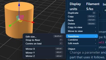
- Duplicate, Copy, Paste and Delete are at the top.
- Copy to view and Move to view send the part to another build plate (chapter 16).
- Transform: change the size, drop it to the floor, centre it or mirror it.
- Combine: join parts, cut them and make holes (chapter 9).
- Edit mesh: cut the part in two, split it into pieces, lay it on a face or hollow it out.
- Arrange (two or more parts): group them, line them up or space them out evenly.
- Object: lock the part so it can't be moved by accident, hide it, show it see-through, save it to My Shapes, or download only this part.
You can give every item in this menu your own key. See chapter 20.
8Placing parts
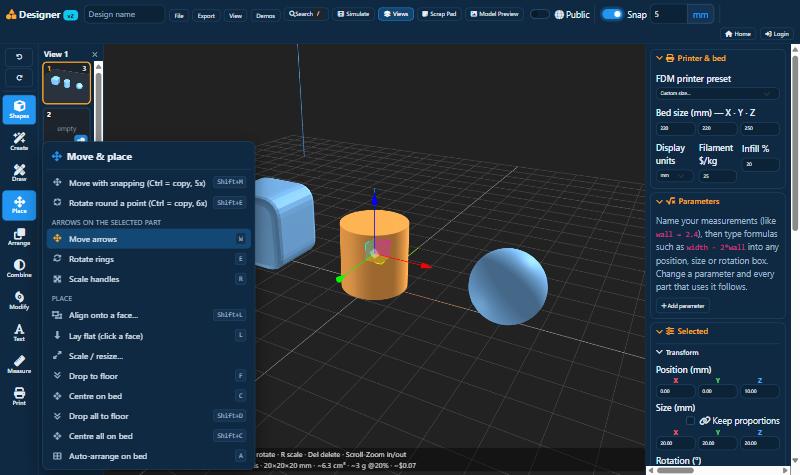
| F | Drop to floor puts the part down on the bed. Always do this before printing, otherwise the part starts in mid-air. |
| C | Centre on bed moves the part to the middle of the bed. |
| Shift+D, Shift+C | Do the same for all parts at once. |
| L | Lay flat: click a flat face of the part and it turns so that face is on the bed. Good for a clean first layer. |
| Shift+L | Align onto a face: click a face of one part, then a face of another part. The first part is placed flat against the second. |
| A | Auto-arrange on bed spreads the parts out so they don't touch. |
| Shift+E | Rotate round a point: click the point to turn around, then turn the part. Type an angle if you want an exact one. |
9Joining parts, holes and cuts
This is how you turn simple shapes into real objects. Click Combine on the tool rail.
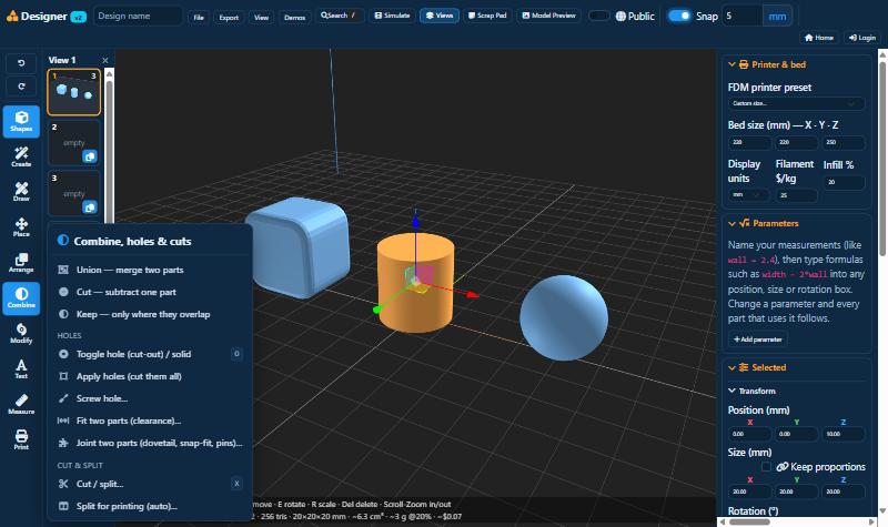
Union, Cut and Keep
Select two parts that overlap, then choose one of these:
- Union joins them into one part.
- Cut takes the second part away from the first, like a cookie cutter.
- Keep keeps only the area where the two parts overlap.
Making a hole
The easiest way to cut something out is with a hole part. A hole part is see-through, and you can keep moving and resizing it until it is in the right place.
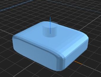
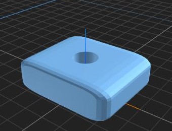
- Add a cylinder (or any other shape) and put it where you want the hole. Make it a bit taller than the block, so it goes right through.
- Select it and press O, or right-click and choose Combine > Mark as hole. It becomes see-through.
- Move or resize it if you need to. You can mark more than one hole.
- Choose Apply holes (Shift + H). All the holes are cut out of the parts they touch.
Also in this group
- Screw hole makes a hole for a screw or bolt, with room for the head or a six-sided pocket that holds a nut.
- Fit two parts leaves a small gap between two parts so they fit together after printing, like a lid on a box.
- Joint two parts adds a dovetail, snap-fit or pins so two printed pieces lock together.
- Cut / split (X) cuts a part in two with a flat cut, for example to print a tall model in two halves.
- Split for printing cuts a model that is too big for your printer into pieces that fit, with pins to join them again.
10Changing a shape
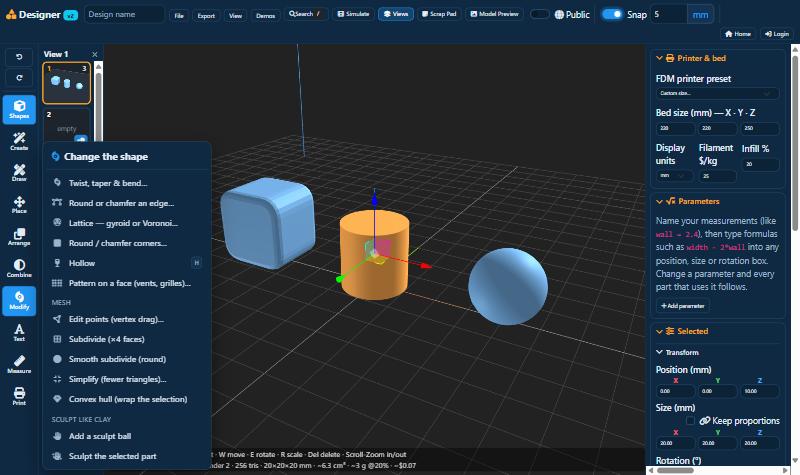
- Twist, taper & bend: twist a box into a spiral vase, make it narrower at the top, or bend it.
- Round or chamfer an edge: click an edge to round it off or give it a slanted cut.
- Round / chamfer corners does all the corners of a part in one go.
- Hollow (H) makes the part a shell with walls as thick as you choose. It saves a lot of filament, and turns a solid block into a box or a cup.
- Lattice (gyroid or Voronoi) turns a model into an open web. Voronoi gives the well-known cell pattern. You choose how many cells you want, and the outside edges stay closed.
- Pattern on a face puts vents, grilles or rows of holes on a flat face.
- Edit points lets you drag the corners of a shape by hand.
- Smooth subdivide rounds off a blocky shape.
- Simplify makes a very detailed imported model lighter, so the Designer stays quick.
- Sculpt lets you push and pull the surface with a brush, like clay.
Try them out. If you don't like the result, press Ctrl + Z and it is back the way it was.
11Drawing your own shapes
If the shape you need isn't in the list, you can draw it. Click Draw on the tool rail.
Drawing on a part
- Choose Draw on a face (Shift + R) and pick Rectangle, Circle, Polygon or Lines.
- Click on a flat face of your part and draw. Points snap to corners and edges. You can also type a size, for example 40,20 and Enter for a rectangle of 40 by 20 mm.
- Choose Push/Pull (Shift + P) and drag what you drew. Push it in for a hole or pocket, or pull it out for a raised part.
Sketching a new shape
- Pick a plane (the bed, the front or the side), draw a rectangle, circle or polygon, and it is pulled up into a solid shape.
- Revolve a profile: draw half the outline of a vase, cup or bottle, and it is turned round into a round object.
- Sweep along a path: draw a path, and a tube or bar follows it.
- Offset a face draws a border on the inside of a face. Follow Me runs a profile around the edge of a face, like the moulding on a picture frame.
12Ready-made parts and makers
Click Create on the tool rail. Each item asks a few questions, such as the size, the number of teeth or the text, and then builds the part.
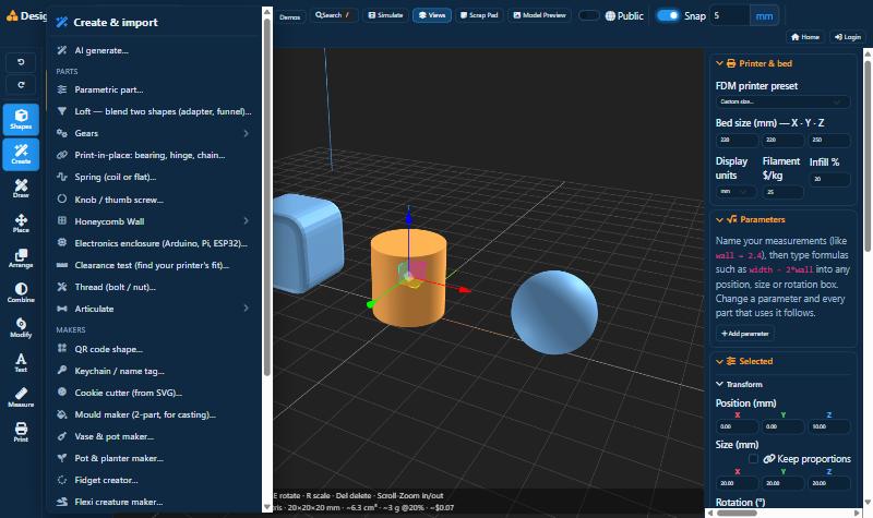
- AI generate (Supporter): describe what you want, for example "a desk organiser with three pen holes and a phone stand, 120 mm wide". The AI builds it from normal parts, so you can change it afterwards.
- Parts: gears, bearings and hinges that print in one piece, springs, knobs, screw threads, boxes for electronics, a honeycomb wall system, and models with moving joints.
- Clearance test: a small test print that shows how much gap your printer needs between moving parts.
- Makers: QR codes, keychains and name tags, cookie cutters, two-part moulds for casting, vases and plant pots, fidget toys, flexi animals, grips and multi-colour keychains.
- Bring in: open a model you already have (STL, OBJ, 3MF, GLB, FBX), turn an SVG drawing into 3D, or add a Reference image to trace over.
13Text, pictures and colour
Click Text on the tool rail.
- 3D text: type your text and choose the font, size and height. It stands on the bed as a separate part.
- Text on a face (T): click a face of a part and type. The letters can stand out from the face or be cut into it.
- Wrap text on a surface puts text around a curved surface, like a name on a mug.
- Image / QR emboss presses a picture, logo or QR code into a face, or raises it out.
- Decal on a surface puts text or a picture onto any surface, also a curved one.
- Apply text / image to the shape makes the text or picture a fixed part of the shape.
- Paint faces gives single faces their own colour, for multi-colour printing.
14Measuring
Click Measure on the tool rail.
| M | Measure: click two points to see the distance between them. You can also measure an angle or the width of a round hole. |
| Shift+T | Tape measure & guides: measure, and leave guide lines and points that other tools snap to. Guides are saved with the design but not printed. |
| Shift+A | Protractor: guide lines at an exact angle. |
| Section view: cut the model open on screen to look inside. | |
| Dimension labels: show the sizes of the selected part in the view. |
15Copies, mirrors and groups
Click Arrange on the tool rail.
- Duplicate (D) puts a copy next to the original.
- Mirror flips a part left to right, front to back, or upside down. Mirror copy makes a flipped copy, for example a left and a right bracket.
- Row, ring and grid of copies make many copies at once: a row of pegs, holes in a circle, or feet in a grid.
- Align (two or more parts) lines parts up by their left sides, centres, tops, bottoms and so on.
- Even spacing (three or more parts) puts the same gap between all of them.
- Group (G) joins parts so they move and resize together. Ungroup (U) separates them again.
- Split into separate bodies turns an imported model that is really several pieces into separate parts.
16Build views
One design can have up to ten build views. Each view is a printer bed of its own. You can use them for:
- parts of one project that are printed separately, for example a box on view 1 and its lid on view 2,
- different versions of the same idea,
- a full bed of parts, with a spare view next to it.
The pictures beside the tool rail show all ten views. The view you are on has an orange frame.
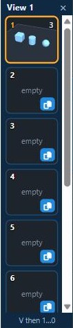
- To go to a view, click its picture, or press V and then the number of the view. V 0 is view 10.
- To copy parts to another view, select them and click the small copy button on that view's picture. Hold Shift to move them instead. You can also right-click and choose Copy to view or Move to view.
- The Views button in the top bar shows or hides the pictures.
- Export downloads the view you are on. Export > All views as 3MF downloads all of them.
When you save, all ten views are saved together.
17Getting ready to print
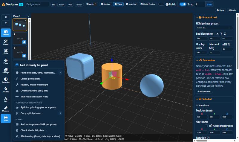
- Print info (P) shows the size, roughly how long the print takes, and the filament and cost.
- Check printability looks for things that would spoil a print, such as gaps in the surface or walls too thin to print, and tells you how to fix them.
- Repair / make watertight fixes most of those problems for you. It is useful for models you downloaded from the internet.
- Overhang view colours the areas that hang in the air and need supports.
- Thin-wall check shows walls that are too thin for your printer.
- If a model is too big for your printer, Split for printing cuts it into pieces that fit, with pins to join them.
- Pack onto plates spreads a lot of parts over as many printer plates as needed.
- 2D drawing makes a drawing of the front, side and top with all the sizes, which you can print on paper.
18Saving and opening designs
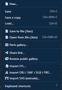
- Type a name for your design in the Design name box at the top.
- Save (Ctrl + S) saves the design to your account, so you can open it on any computer. Save a copy saves it as a new design and leaves the old one as it was.
- Load (Ctrl + O) shows your saved designs, each with a small picture.
- Save to file and Open from file keep the whole design as one file (.litez) on your own computer. Use this for backups, or to give a design to someone else.
- New starts an empty design.
- Share link gives you a link that other people can open to see your design.
- Switch on Public at the top before you save, and your design is shown in the public Gallery. Other people can then open a copy of it and change their copy. Your own design stays as it is.
- Import brings in a model or drawing you already have (STL, OBJ, 3MF, GLB, FBX or SVG).
19Downloading for your printer
Your printer can't read a design directly. You download a file and open it in your slicer. That is the program that came with your printer, such as Bambu Studio, PrusaSlicer, OrcaSlicer, Cura or Creality Print.
Open the Export menu and choose a format.
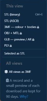
| Format | When to use it |
|---|---|
| STL | Every printer and slicer can open it. It has no colour. Shortcut: Ctrl + E. |
| 3MF | For printing in more than one colour, or when you want the parts kept separate in the slicer. |
| OBJ, GLB, PLY | For other 3D programs, websites or AR. |
| Selected as STL | Only the selected part, not the whole design. |
| All views as 3MF | All your build views at once. |
A padlock next to a format means it needs Supporter. STL is free for everyone with a free account.
20Keyboard shortcuts
Most things have a key, which saves a lot of clicking. Press ? or choose File > Keyboard shortcuts to see them all.
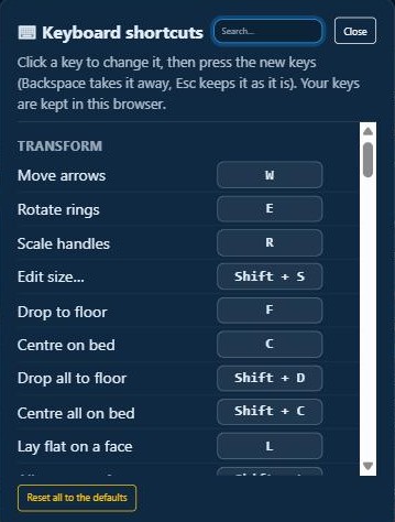
Changing a key or adding one
- Press ? to open the window. Type in the search box to find what you want, for example "floor".
- Click the key button next to it. It now waits for you to press a key.
- Press the new key or keys, for example Alt + F. If that key is already used for something else, you are asked first whether to swap them.
- Press Backspace while it waits to remove the key, or Esc to leave it unchanged.
- Reset all to the defaults puts all the keys back the way they were.
- You can give a key to every item in the right-click menu and to every tool in the menus on the left (Shapes, Create, Draw and the others). Tools that have no key yet are listed under their menu's name. The menus then show your key next to the item.
- Your keys are saved in this browser.
All the standard keys are listed on the quick reference card at the back.
21Other useful things
- Search (/): type a word to find a shape or tool.
- Undo and Redo: the two arrows at the top of the tool rail, or Ctrl + Z and Ctrl + Y.
- Snap: when it is on, parts move in steps (type the step in mm next to it). When it is off, they move freely.
- Scrap Pad: a notepad for measurements and ideas. You can drag it anywhere and make it bigger or smaller.
- Model Preview: a small window for a photo or drawing of what you are making, so you can look at it while you work. Drop or paste a picture into it.
- Simulate: watch your model being printed, layer by layer.
- Demos: finished example designs to open and learn from.
- Lock (K): a locked part can't be selected or moved by accident. Unlock it in the Objects list.
- Hide (Alt + H): hide a part so you can get to what is behind it. The eye button in the Objects list shows it again.
The 3D Designer app
The Designer is also available as an app for Windows and Mac. It runs in its own window instead of the browser. You sign in with your 3d-lithophane.com account, and you see the same saved designs as on the website. You can download it from the Downloads page.
22Problems and fixes
| Problem | What to do |
|---|---|
| A part is floating, or sits inside the bed | Select it and press F (drop to floor). Shift + D does all parts. |
| The hole wasn't cut | Make the hole part a bit longer so it sticks out on both sides, then choose Apply holes (Shift + H). |
| I can't click a part | It is probably locked or hidden. Check the Objects list in the right panel. |
| Two parts print as two pieces | Let them overlap a little, select both and choose Union. |
| My model lost its colours | STL files have no colour. Download a 3MF instead. |
| It is too big for my printer | Tick Keep proportions and make it smaller, use Place > Scale / resize > Fit bed, or use Split for printing. |
| The Designer is slow | Use Simplify on big imported models, and hide the parts you are not working on. |
| I lost my design | Open the Designer again in the same browser. It offers to bring back work that wasn't saved. Press Ctrl + S often. |
| A key does nothing | Click once in the 3D view first, because the key may be going into a text box. Also check the key in the shortcuts window (?). |
| There is a padlock | That tool or format needs Supporter. Everything else still works. |
The full help, with more detail on every tool, is at 3d-lithophane.com/designer-guide.php.
23Quick reference card
These are the standard keys. You can change any of them (chapter 20).
Looking around
| Left-drag | Turn around |
| Right-drag | Slide |
| Scroll wheel | Zoom |
| 1 2 3 4 | Angle, front, side, top |
| Shift+W | Display style |
| V then 1…0 | Go to build view |
Edit
| Ctrl+Z / Y | Undo / redo |
| Ctrl+C / V | Copy / paste |
| Ctrl+A | Select all |
| D | Duplicate |
| Delete | Delete |
| Tab | Next part |
| Arrow keys | Nudge (Shift: 0.2 mm) |
Move and size
| W E R | Move, rotate, scale |
| Shift+S | Edit size |
| F / Shift+D | Drop to floor / all |
| C / Shift+C | Centre / all |
| L | Lay flat on a face |
| Shift+L | Align onto a face |
| A | Auto-arrange |
| Alt+X/Y/Z | Mirror |
| Shift+M | Move with snapping |
| Shift+E | Rotate round a point |
Combine
| Alt+U | Union |
| Alt+S | Cut |
| Alt+I | Keep |
| O | Hole / solid |
| Shift+H | Apply holes |
| X | Cut / split |
| Shift+X | Split into parts |
| H | Hollow |
Parts
| G / U | Group / ungroup |
| Alt+B | Align bottoms |
| K | Lock / unlock |
| Alt+H | Hide |
| Alt+W | See-through (this part) |
Draw and measure
| Shift+R | Draw on a face |
| Shift+P | Push / pull |
| Shift+O | Offset a face |
| Shift+F | Follow Me |
| T | Text on a face |
| M | Measure |
| Shift+T | Tape measure |
| Shift+A | Protractor |
| Shift+I | Reference image |
| P | Print info |
File
| Ctrl+S | Save |
| Ctrl+Shift+S | Save a copy |
| Ctrl+O | Load a design |
| Ctrl+Shift+O | Open a file |
| Ctrl+E | Export STL |
| Ctrl+Shift+E | Export this part |
Help
| / | Search all tools |
| ? | Keyboard shortcuts |
| Esc | Cancel or close |
3d-lithophane.com